
High voltages and moving parts around motors and motor driven equipment can cause serious or fatal injuries, so be careful when installing, operating and maintaining electrical equipment. Be familiar with and follow all local electrical and safety codes, as well as NEMA MG2, (Safety Standard for Construction and Guide for Selection, Installation and Use of Electrical Motors and Generators), the National Electrical Code (NEC), and the Occupational Safety and Health Act (OSHA).
Copies of the National Electrical Code may be ordered from the National Fire Protection Association on their web site: www.nfpa.org, or contact your local government inspection agency. NEMA Standards (including MG2) may be ordered from the National Electrical Manufacturers Association, on their website: www.nema.org. Contact the U.S. Government Department of Labor for availability of OSHA requirements.
For hazardous locations (explosive atmospheres) as defined by Article 500 of the NEC and local codes, an explosion-proof motor may be required. Refer to both Article 200 of the NEC and your local government inspection agency or insurance company inspector for guidance and detailed information on proper motor selection and protection.
Most motors are equipped with thermal protectors which prevent damage due to overloading and stalled conditions. These motors have the words “Thermally Protected” on the nameplate. The protector may be of the automatic or manual type. An automatic protector turns the motor off if it is overloaded or operated under abnormal conditions; after a cool down period it turns the motor back on. Motors with manual protectors have a red button which pops up if the protector trips. After a cool down period the protector can be re-set by pushing this button until a click is heard. The motor will then re-start immediately.
MOTORS WITH AUTOMATIC RESET THERMAL PROTECTORS SHOULD NOT BE USED WHERE UNEXPECTED STARTING OF THE EQUIPMENT MIGHT CREATE A HAZARD, APPLICATIONS SUCH AS POWER TOOLS, FOOD CHOPPERS, ETC. SHOULD USE MOTORS WITH MANUAL RESET PROTECTORS.
Motors not provided with thermal overload protection should be installed using proper remote overcurrent protection against burnout under abnormal conditions of above-rated load or a stalled motor. Selection of this device should be done by a qualified electrician.
All moving parts must be guarded to prevent personal injury. Guard all propeller fans, exposed blowers, couplings, belts, sheaves, flywheels, and etc. Keep fingers and foreign objects away from ventilation and other openings. Do not insert any object into the motor. Remove the shaft key before running the motor without a connected load to avoid the key flying out. (Caution: shaft keyway edges are sharp) Be careful when touching the exterior of a motor that is in use, as it may be hot enough to be painful or cause injury. This condition is normal for most motors when operated at rated load and voltage.
Upon receipt of the motor, check for carton damage. After opening carton, look for concealed damage such as damaged conduit box, bent base or cracked castings. Verify that shaft turns by hand. While turning shaft check for unusual noises, scraping sounds, binding or tight spots. Single phase motors normally have a slight rubbing sound from the centrifugal switch mechanism. Check the nameplate to verify that data conforms to specifications of motor ordered, and connection diagram agrees with lead labeling. If any discrepancy is found, consult dealer from whom the motor was purchased. Never pick up a motor by its leads or shaft since this could cause damage.
ALWAYS DISCONNECT THE POWER SOURCE BEFORE WORKING ON A MOTOR OR ITS CONNECTED LOAD.
To connect motor for proper voltage and rotation, refer to connection diagram on nameplate or inside terminal/conduit box.
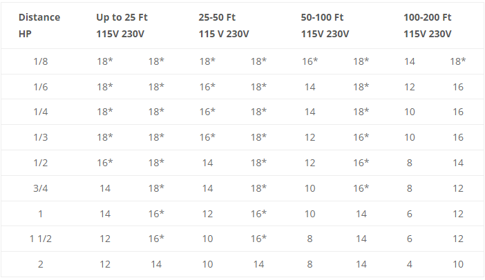
All aspects of the installation must conform to the requirements of the NEC, including Article 430 (Motor Circuits and Controllers), and all local codes. Wherever possible, each motor should be powered from a separate circuit of adequate capacity to keep voltage drop to a minimum during starting and running. Increase wire size where motor is located a distance from the power source; wire size must be adequate to minimize voltage drop during starting and running-Refer to Table A for suggested wire sizes. Portable cords, if used, should be as short as possible to minimize voltage drop. Long or inadequately sized cords, especially on hard starting loads, can cause a reduction in motor life or nuisance overload tripping.
Insulate all connections carefully to prevent grounding or short-circuits. Sharp edges on terminals require extra protection. Tape wire nuts to prevent loosening. For safety and to prevent entry of contaminants, reinstall all conduit and terminal box covers. Do not force connections into the conduit box.
THE MOTOR FRAME MUST BE SECURELY AND ADEQUATELY GROUNDED to the equipment grounding conductor by using the grounding cord, green screw or green wire provided. The grounding wire must be no smaller than the supply wiring. Refer to NEC Article 250 (Grounding) for additional information. All wiring should be done by a qualified electrician.
Determine rotation before coupling to driven equipment. Remove shaft key before operating motor at no-load. On three phase motors, interchange any two line leads (not motor leads) to reverse rotation.
ALWAYS DISCONNECT THE POWER SOURCE BEFORE WORKING ON A MOTOR OR ITS CONNECTED LOAD.
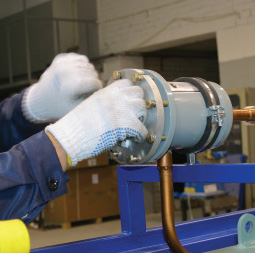
Motors must be securely fastened to a rigid, flat surface to prevent vibration and minimize noise. Adjustable motor base and rails are often used for easy and accurate belt adjustment. For secure mounting, use high quality bolts of the largest possible diameter. Before tightening bolts, make sure all four mounting pads of the base are in contact with mounting surface. Add shims as required to prevent possible bending or cracking of the motor base. When installing NEMA C-Face or other face-mounted motors, mounting surfaces must be clean and free from burrs. Check for proper seating and alignment by turning shaft manually.
Belt drive sheaves must be in line. Use a straight edge to check. In general, the closer sheaves are mounted to motor bearing, the less the bearing load. The inner edge of sheave rim should be as close to the face of the motor as possible, but not closer than shoulder on shaft. The center point of belt or system of V-Belts must not be beyond the end of the motor shaft.
Do not strike shaft with hammer or other tool. Do not force sheave or coupling on shaft; forcing can cause bearing damage. Belt tension should be appropriate for the specific application to prevent slippage or excessive belt tension. Excessive tension will shorten belt life and damage bearings. On direct-drive installations carefully check shaft and coupling alignment. Shim as required. Do not depend on a flexible coupling to compensate for Misalignment; its only function is to isolate noise and dampen torque pulsations.
On direct-drive installations carefully check shaft and coupling alignment. Shim as required. Do not depend on a flexible coupling to compensate for misalignment; its only function is to isolate noise and dampen torque pulsations.
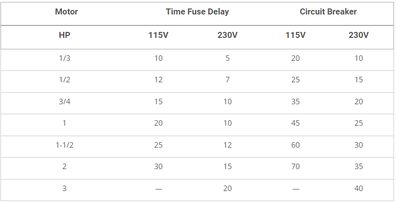
Although your Bluffton Motor Works motor may be equipped with an overload protector, you must provide a correctly sized fuse at the breaker box.
Wiring connections are located on the motor nameplate. Be sure the voltage connection matches that of the supply line. If reconnection is required refer to the nameplate. For troubleshooting purposes, please contact the factory with your motor model number for more detailed assistance.